එළකිරි Circuit පන්තිය

udarapath

Active member
  • Apr 16, 2008
    2,016
    253
    31
    Pissan Kotuwe
    එළකිරි Circuit පන්තිය

    Circuit හදන්න ආසාවක් තියෙන අය එන්න හරිම සරලව කියල දෙන්නම් :yes::yes:
    හරි ඔන්න පටන් ගමු. මුලින්ම සරල Circuit හදන විදිය කියල දෙන්නම් කෝ ;);)
    ඉස්සෙල්ලම ඔයාලට මෙන්න මේ Item ටික ඉගෙන ගන්න වේවි නෙත්නම් sry ටමා :eek::eek:

    මේ symbols වලින් ටමා අපිට පරිපථයට ඕන වෙන Items අඳුරගන්න පුළුවන් වෙන්නේ

    Transistor
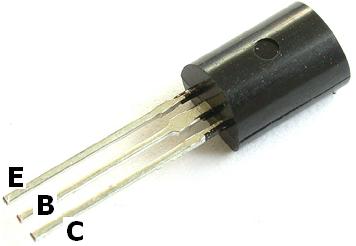
    labelled-transistor.jpg


    Transistor.jpg


    Capacitors
    2011-08-13_073724_capacitor.jpg


    capele.gif


    LED
    led.jpg


    250px-LED_symbol.svg.png


    Resister
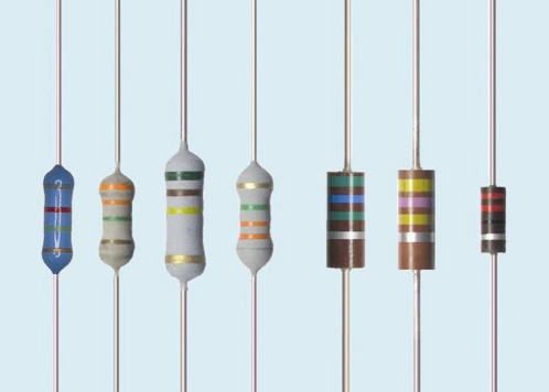
    Resistors.jpg


    Symbol-of-resistor.JPG


    Batteries


    battery_symbol.gif


    දැන් ඉතින් අපි Circuit හදද්දී දන ගන්න ඕනේ මුලික symbols දැනගත්ත නේ දැන් ඉතින් පොඩි simple cirucuit එකක් කියල දෙන්නම්


    Simple LED flasher circuits
    By simple, I mean that these circuits only flash one or two LEDs. This is opposed to the light chaser circuits that can flash four or more. Of course, the simplest LED flasher is simply to use a flashing LED. The problem with that approach is you have no control over the flash rate, but it does have its use for eye catching displays for selling stuff. The circuits below give you that control, plus they can flash two LEDs alternately.
    There are many possible applications for the circuits below, especially for kids, who love flashing lights. Here's some possible uses.

    • Railroad crossing signal for model railroads.
    • Safety blinkers for bicycles, etc.
    • Fun stuff for Halloween, like making those plastic Jack-O-lanterns blink (try using ultraviolet LEDs here).
    • Christmas decorations.
    • Blinkers to locate items in the dark.
    Transistor LED flasher
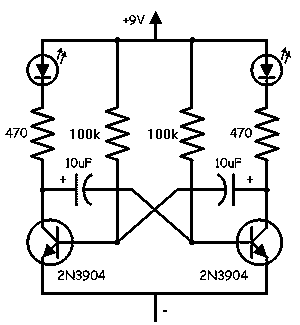
    t-flash2.gif
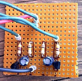
    This circuit has a lot going for it. For one thing, it only consists of two transistors, two capacitors and four resistors. That also means it consumes very little power. You can control the flash rate by changing the size of the 100k resistors (100k makes for a pretty slow rate). You can also control the duty cycle by using resistors of different values on the two sides. The 470 ohm resistors control the current through the LEDs. Normally you want to limit this to 20mA, but to conserve battery power, you may need to limit it even further. You can also connect several LEDs in series, instead of using only one for each side. With red LEDs (1 per side) and the values shown, the circuit draws about 11mA. Here's what the actual circuit looks like:

    t-flash.jpg
    On this circuit, the green wires connect to the LEDs, but you can mount them on the actual circuit board for some applications. The picture is about twice actual size. Here is an example of the use of this circuit:

    jl.gif


    Subscribe-Via-Email.gif


    + Rep +

     
    Last edited:

    udarapath

    Active member
  • Apr 16, 2008
    2,016
    253
    31
    Pissan Kotuwe
    අඳුරු වැටුනම පත්තු වෙන Light එකක්

    A Simple and Cheap Dark-Detecting LED Circuit

    Here's a simple problem: "How do you make an LED turn on when it gets dark?" You might call it the "nightlight problem," but the same sort of question comes up in a lot of familiar situations-- emergency lights, street lights, silly computer keyboard backlights, and the list goes on.
    Solutions? Lots. The time-honored tradition is to use a circuit with a CdS photoresistor, sometimes called a photocell or LDR, for "light-dependent resistor." (Circuit Example 1, Example 2.) Photoresistors are reliable and cost about $1 each, but are going away because they contain cadmium, a toxic heavy metal whose use is increasingly regulated. There are many other solutions as well. Look heretricks used in well-designed solar garden lights, which include gems like using the solar cell itself as the sensor. (Our own solar circuit collection is here.) for some op-amp based photodetector circuits with LED output, and check out some of the
    In this article we show how to build a very simple-- perhaps even the simplest-- darkness-activated LED circuit. To our LED and battery we add just three components, which cost less than thirty cents altogether (and much less if you buy in bulk). You can build it in less than five minutes or less (much less with practice).
    What can you do with such an inexpensive light-controlled LED circuit? Almost anything really. But, one fun application is to make LED throwies that turn themselves off in the daytime to save power. Throwies normally can last up to two weeks. Adding a light-level switch like this can significantly extend their lifetime.


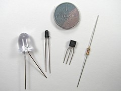
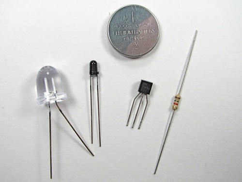
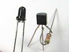
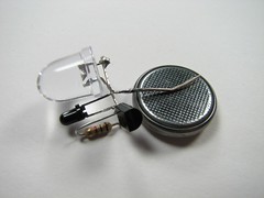
    Here are our components: On top: a CR2032 lithium coin cell (3 V). On the bottom (L-R): the LED, an LTR-4206E phototransistor, a 2N3904 transistor, and a 1 k resistor. This LED is red, blindingly bright at 60 candela, in a 10 mm package. It casts a visible beam, visible for about twenty feet in a well-lit room. We got the LEDs and batteries on eBay, and the other parts are from Digi-Key, but Mouser has them as well. As we mentioned, the last three cost about $0.30 all together, and much less in bulk.
    The LTR-4206E is a phototransistor in a 3mm black package. The black package blocks visible light, so it is only sensitive to infrared light-- it sees sunlight and incandescent lights, but not fluorescent or (most) discharge lamps-- it really will come on at night.
    Our starting point is the simplest LED circuit: that of the LED throwie, which has an LED driven directly from a 3V lithium coin cell. (Funny looking example here.) From this, we add on the phototransistor, which senses the presence of light, and we use its output to control the transistor, which turns the LED on.


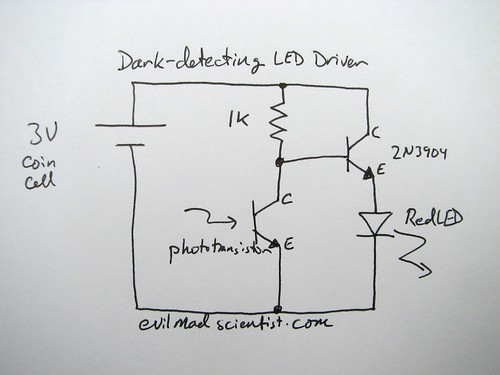
    The circuit diagram looks like this; please ignore the messy handwriting. ;)
    When light falls on the phototransistor, it begins to conduct up to about 1.5 mA, which pulls down the voltage at the lower side of the resistor by 1.5 V, turning off the transistor, which turns off the LED. When it's dark, the transistor is able to conduct about 15 mA through the LED. So, the circuit uses only about 1/10 as much current while the LED is off. One thing to note about this circuit: We're using a red LED. That's because the voltage drop across the transistor allows less than the full 3 V across the LED. The full three volts is really only marginal for driving blue LEDs anyway, so two-point-something really doesn't cut it. (Might be able to work around that with a cheap FET-- haven't tried yet.)
    And now, let's build it. You can certainly put this together on a breadboard, but there's something more satisfying about the compact and deployable build that we walk through here.


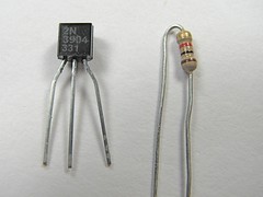
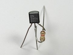
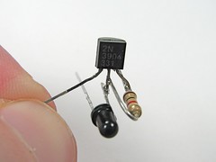
    First get the transistor and the resistor. The pins of the 2N3904 are called (left-to-right) Emitter, Base, Collector, when viewing it from the front such that you can read the writing. We're going to solder the resistor between the leads of the Base and Collector of the transistor. Unusual part: hold the resistor with its leads at 90 degrees to those of the transistor while you solder.
    Stay safe when you do this: Use Mr. Hands.
    After soldering, clip off the excess resistor lead that is attached to the transistor base (middle pin), as well as the excess length of the collector pin.


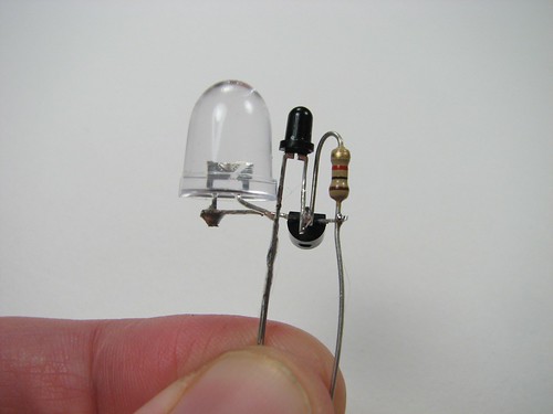
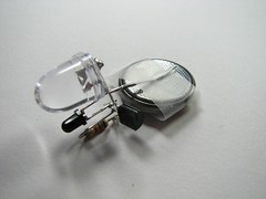
    Next, we add the phototransistor. Note that it has a flatted side, much like an LED does. This pin on that side is the collector of the phototransistor. Solder the collector (flatted side) to the middle pin (the base) of the transistor, again at 90 degrees. The other pin of the phototransistor, the emitter, is left unconnected for the moment. (Here is an alternate view of what that should look like when you're done.)
    Finally, we need to add the LED. To do so, we need to know which side is the "positive," or anode side of the device. Regrettably markings of LEDs are not consistent, so the best way to be sure is to test it with the lithium coin cell-- put the LED across the terminals of the cell and, when it lights up, note which side is touching the (+) terminal. (Usually, it's the one with the longer lead.) Solder the "positive" lead of the LED to the emitter pin of the transistor-- it's the one on the left, which doesn't have anything soldered to it. Trim away the excess lead of the LED that goes past the solder joint. Solder the other pin of the LED (the "negative" pin, or cathode) to the emitter of the phototransistor, the pin on the non-flatted side, which does not have anything connected to it yet.


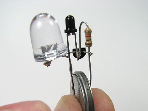
    By this point, there are only two pins sticking down below the components: One that goes to the resistor and collector (rightmost pin) of the transistor, and one that goes to the emitter of the phototransistor and to the cathode of the LED.


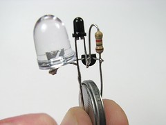
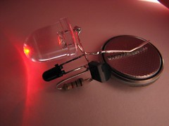
    To test the circuit, squeeze the coin cell between these two terminals, positive side goes to the lead touching the resistor. You can't see the LED on here because these photos were taken with incandescent lighting-- it wouldn't turn on.


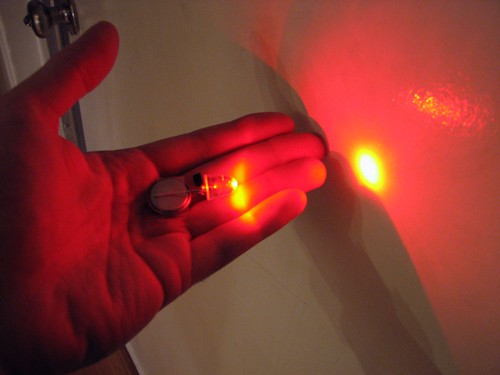
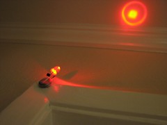
    Bending the leads to contact the lithium cell a little more reliably, you can try it out a little more easily. In the photo on the right, I cupped my hand over the circuit-- so the LED turned on.


    • Like
    Reactions: wisal

    udarapath

    Active member
  • Apr 16, 2008
    2,016
    253
    31
    Pissan Kotuwe
    Electronic Dice


    Download PDF version of this page

    dice.gif
    Press the push switch to 'throw' the dice: this makes the circuit rapidly cycle through the dice numbers so that an effectively random dice number is displayed by the LEDs when the push switch is released.
    Drill seven 5mm holes in a dice pattern to mount the LEDs on a panel such as a plastic box lid or sheet of thin plywood. They should be a tight fit but a little glue can be applied from the underside if necessary.

    diceseq.gif
    The 555 astable circuit provides clock pulses at about 5kHz for the 4017 counter which has ten outputs (Q0 to Q9). Each output becomes high in turn as the clock pulses are received. Only six counts (Q0-Q5) are needed so Q6 is connected to reset. Appropriate outputs are combined with diodes to supply the LEDs: for example Q1, Q3 and Q5 are combined for LED A.
    The dice sequence has been started at 2 so the ÷10 output can be used for LEDs B1 and B2, this saves diodes and simplifies the circuit. Pressing the push switch makes the disable input low so that counting occurs.

    This project uses a 555 astable circuit to provide the clock pulses for the 4017 counter.
    Parts Required


    • resistors: 330 ×3, 470, 10k ×3
    • capacitors: 0.01µF, 0.1µF
    • diodes: 1N4148 ×6
    • LEDs: red 5mm diameter ×7
    • 555 timer IC, such as NE555
    • 4017 counter IC
    • DIL sockets for ICs: 8-pin, 16-pin
    • on/off switch
    • push switch
    • battery clip for 9V PP3
    • stripboard: 20 rows × 22 holes

    Stripboard Layout

    dicesb.gif


    Circuit diagram

    dicecd.gif
     

    udarapath

    Active member
  • Apr 16, 2008
    2,016
    253
    31
    Pissan Kotuwe
    Traffic Light Project


    Download PDF version of this page

    trafficlseq.gif
    trafficlight.gif
    This project operates red, amber and green LEDs in the correct sequence for a single UK traffic light. The time taken for the complete red - red & amber - green - amber sequence can be varied from about 7s to about 2½ minutes by adjusting the 1M preset. Some amber LEDs emit light that is almost red so you may prefer to use a yellow LED.
    The 555 astable circuit provides clock pulses for the 4017 counter which has ten outputs (Q0 to Q9). Each output becomes high in turn as the clock pulses are received. Appropriate outputs are combined with diodes to supply the amber and green LEDs. The red LED is connected to the ÷10 output which is high for the first 5 counts (Q0-Q4 high), this saves using 5 diodes for red and simplifies the circuit.

    This project uses a 555 astable circuit to provide the clock pulses for the 4017 counter.
    Parts Required


    • resistors: 470 ×3, 22k, 100k
    • capacitors: 0.1µF, 1µF 16V radial, 10µF 16V radial
    • diodes: 1N4148 ×6
    • LEDs: red, amber (or yellow), green
    • 1M preset, horizontal
    • 555 timer IC, such as NE555
    • 4017 counter IC
    • DIL sockets for ICs: 8-pin, 16-pin
    • on/off switch
    • battery clip for 9V PP3
    • stripboard: 20 rows × 21 holes

    Stripboard Layout

    trafficlsb.gif


    Circuit diagram

    trafficlcd.gif
     
    • Like
    Reactions: mcwolfe